3 Floor Elevator Plc Ladder Logic Pdf
Https Www Krishisanskriti Org Vol Image 05aug201707084903 20 20 20 20 20 20 20 20 20 20sanjukta 20behera 20 20 20 20 20 20 20 20 20 20 20 20 20 2040 43 Pdf

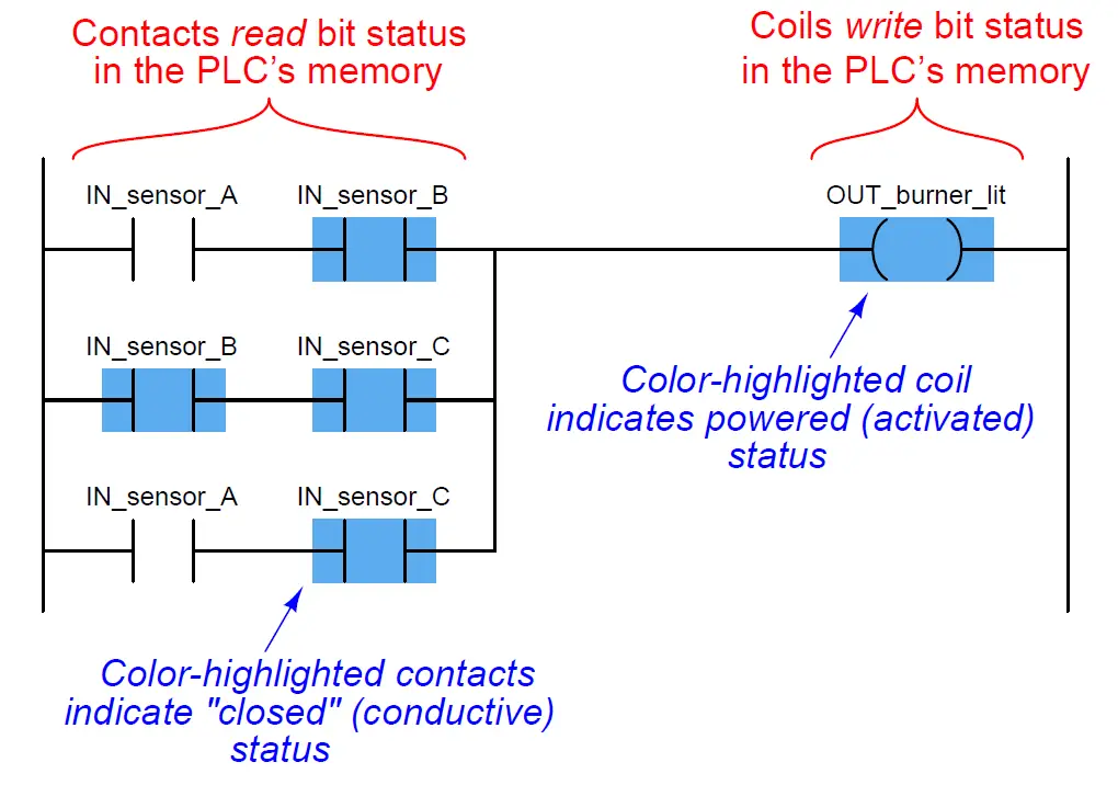
Plc Ladder Logic Symbols Motor Control Circuits Plc Programming Ladder Logic Electrical Circuit Diagram
Https Www Ijser Org Researchpaper Implementation Of A Four Floor Programmable Logic Controlled Elevator System Pdf

Asi Free Full Text Development Of Lift Control System Algorithm And P M E Analysis In The Workplace Html

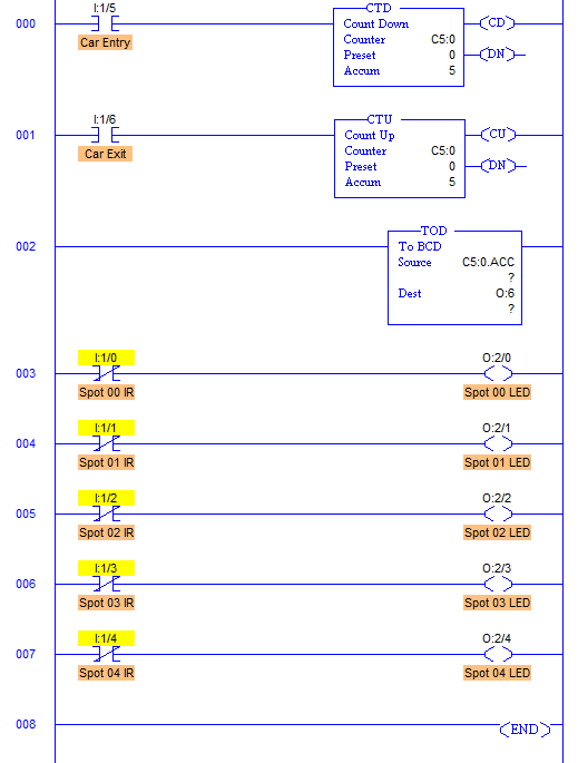
Plc Program For Entry Exit Control Of Car Parking Instrumentation Tools Car Parking Ladder Logic Tutorial
Http Www Internationaljournalssrg Org Ijeee 2019 Volume6 Issue2 Ijeee V6i2p101 Pdf
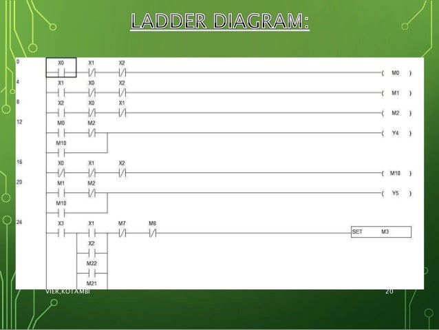
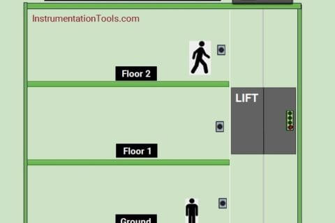
The system is hence divided in 3 modules floor plc and the elevator.
3 floor elevator plc ladder logic pdf.

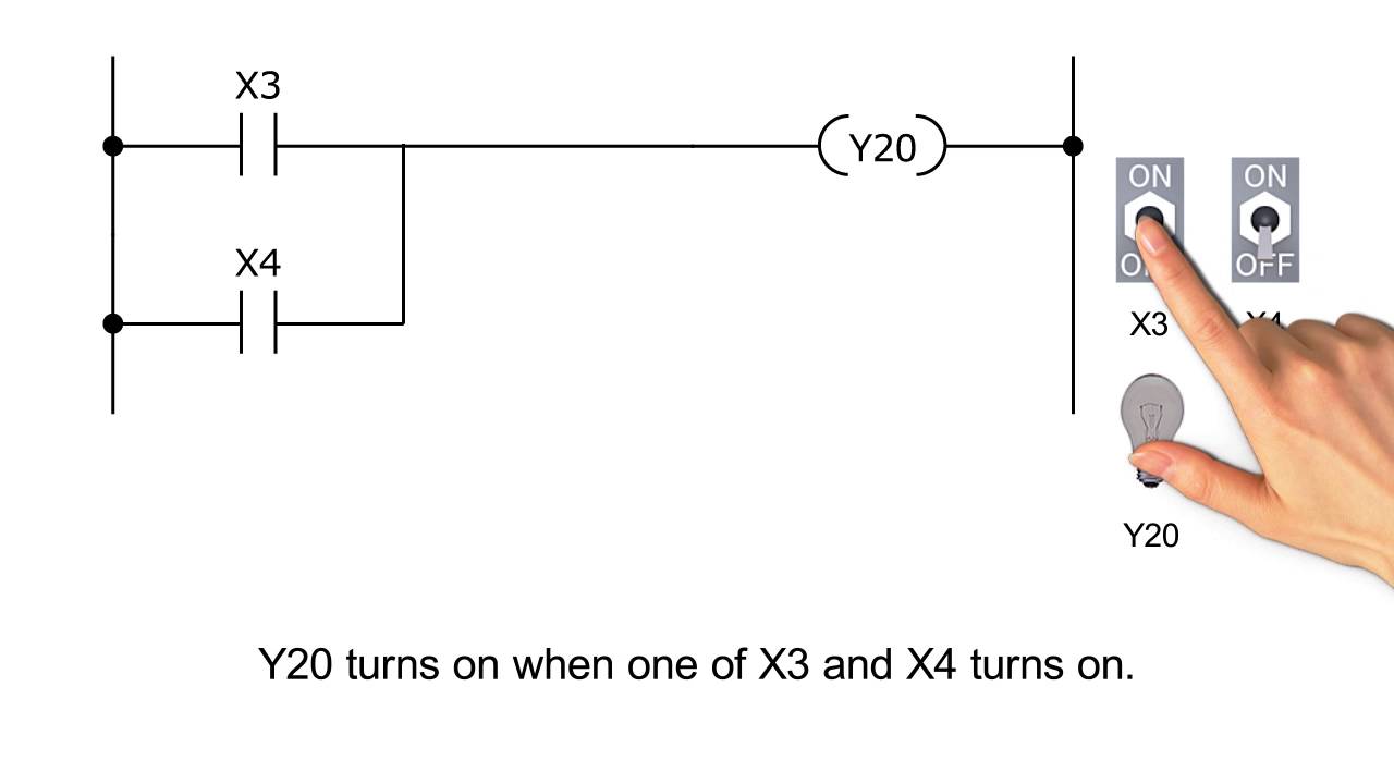
Plc Logic Gate Write A Plc Ladder Logic For And Gate Or Gate Not Gate And Xor Agte Explore Plc Tutorials Ladder Logic Programmable Logic Controllers Logic
Https Www Ijireeice Com Upload 2017 April 17 Ijireeice 2026 Pdf

Plc Elevator Project Youtube
Plc Program For A Car Parking System Sanfoundry

Plc Program Using Logic Gates Ladder Logic Programmable Logic Controllers Logic
Plc Based Elevator Ppt Group 1

Learn Cnc Ladder Logic Cnc Controls Learn Plc Programming And Plc Ladder Logic Circuit Physics

Split Range Control Logic Ladder Logic Logic Control

Lk 6606 Conveyor Belt Ladder Diagram Printable Wiring Diagram Schematic Download Diagram
Ge Fanuc Plc Ladder Logic Examples Archives Instrumentation Tools

Elevator Control Simulation And Code Generation Using Ladder Logic Matlab Simulink

Figure 6 From Design And Practice Of An Elevator Control System Based On Plc Semantic Scholar
Plc Ladder Logic Practice Problems Pdf Archives Instrumentation Tools

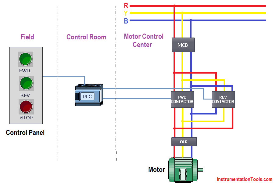
Control Circuit Of A Star Delta Or Wye Delta Forward Reverse Electric Motor Controller A Basic Industrial Electronic Engineering Delta Electrical Engineering

Plc Program For Entry Exit Control Of Car Parking Instrumentation Tools Car Parking Ladder Logic Programming
Plc Ladder Logic Diagram For Elevator Archives Instrumentation Tools
Traffic Light Controlling Using Plc Ladder Programming Android Google Coaching Bka Nat Radionaylamp Com
Plc Programming Examples Animation Archives Instrumentation Tools
Https Encrypted Tbn0 Gstatic Com Images Q Tbn 3aand9gcs6exwlrqyihtdi2ulgxlgtnj1uwvmmwlapwxiapeborg3i1qr Usqp Cau
3 Ladder Program Melsec Tutorial Youtube
Https Pdhonline Com Courses E448 E448content Pdf

Plc Program For Water Level Control Ladder Logic Electronic Schematics Control
Https Mafiadoc Com Download Plc Based Elevator Control System Pdf Document Blikoon 5a2778c21723ddf13eb4c6c0 Html

What Is The Difference Between Pnp And Npn Learn Robotics Learn Robotics Programmable Logic Controllers Ladder Logic
Source : pinterest.com
